Submitted by Ranger Rick

Because of the addition of Saddlemen Jumbo Drifter Saddle Bags to my Aero, it became necessary to relocate my rear turn signals. Since I also planned to add Electrical Connections’ LED Turn Signal Conversion Kit to my bike to increase it’s visibility, I decided to do these both at the same time. The below instructions are assuming you are doing both.
After having done this project... I would consider it fairly difficult. Especially if you are unfamiliar with electrical connections and circuits. If all you’re going to do is move the existing signals... then, it’s not too bad. Total time was approximately 4 hours over two days.
Needed items:
Cruiser Customizing Turn Signal Bracket: www.cruisercustomizing.com / part number CWI-01-202
Electrical Connections Turn Signal Conversion Kit: www.electricalconnection.com/other-lighting/tsk-star&sport.htm
18 gauge electrical wire (in light blue, orange and green)
1/4” and 3/16” cable shrink wrap in 3’ lengths
Misc. electrical crimp connectors, electrical tape, tools, etc.
Removing existing rear turn signals:
Not very difficult. Start by removing the seat. (Two side bolts and one rear bolt.) Find the wiring harness for the rear turn signals (light blue and orange connectors) and disconnect them.
Next take out the 3 bolts that hold the rear chrome fender bracket which the turn signal is attached to. Pull the bracket off the bike and pull the tabs holding the cabling up to release the wiring to the turn signal. With the bracket off the bike, using a “L” wrench, unscrew the bolt holding the light onto the bracket. (I had to use an extension on the L wrench to get enough leverage to “crack” the bolt so it would start turning. Sucker’s on tight!) Replace the chrome bracket on the bike and secure it with the original bolts. Go around and take the other turn signal light off the bike in the same manner.
Disassembling the Turn Signal:
First thing to do is to take the turn signal apart and rewire it. Start by cutting the existing wire on the turn signals. Measure down from the blue or orange connector (opposite end from the turn signals housing) about 4 inches and cut the cable. Remove the protective wrap from the 4 inch section.
Now disassemble the turn signal. Start by taking the screw out of the bottom of the unit. This will release the lens cap which (with a little effort) pops out. Remove the light bulb. Take the two screws in the plate (that holds the bulb) out. Slide the whole assembly out by pulling on the part of the bracket closest to the lens cap. As it slides out, note where the cables behind the bracket are routed to the spring-loaded lamp contact (you’ve got to get the wires back the same way). Next using a small screw driver, pull out the rubber gasket holding the wires where they come into the turn signal’s “bowl” or housing. You can pull the wires gently into the bowl at the same time which will help this process. Once you have access to the wires, pull the rest of the wires into the bowl and then remove the rubber gasket and then the wire’s protective plastic covering.


In the first image above notice the rubber gasket that pulls out and the rubber collar that doesn't move. Also note the new EC splice (orage wire) in the first image, and nthe LED cables inside of the shrink wrap in the first picture, and not in the shrink wrap in the second picture.
Re-wiring the Turn Signal:
Now it is time for you to seriously look at the wiring diagram for the system. Electrical Connections (EC) gives you a great "block diagram" that shows you what goes where. Below is a custom diagram (based on theirs) of how I did it. Note that is absolutely necessary to use both of their red, green & blue "Y" connectors that are supplied with their kit. (EC confirmed to me that they put a few electrical components in the "Y"s shrink wrap that are needed for their LEDs to work properly... so use both!)

Mount the LED rings into the lens caps per EC's instructions. Note that the connections for the wires that attach to the LED ring should be opposite side from where the turn signal cables come into the bowl. (Dry fit this before you "glue" the LED ring into place!) Now, silicon the rings in place and let sit over-night.

Cut and attach one of the two wires that go to the LED ring to the Light Blue or Orange cable in the light's bowl using the supplied splicers from EC. Make sure to leave about 3 inches of LED cable to come out to the LED ring.
Feed the other wire for the LED ring with the other two wires from the turn signal thru the rubber gasket. Cut the LED ring wire to the same length as the other two wires. Insert the 3 wires into a 3/16 inch shrink wrap until it comes up to the rubber gasket. Do not heat the shrink wrap except right at the gasket to hold it in place. (You will heat the rest of it later so it will mold into place around the license bracket housing.) Feed the wrapped wires back out the end of the turn signal and reassemble the entire turn signal. Be very careful about how you route the wires behind the bowl's bulb plate, so to bring the LED connectors out at the correct location. Do the same for the other turn signal.

Building the Wiring Harness:
Next we want to build or "extend" the wiring harness for the new location. I did most of this sitting at my work bench. This harness will have 5 wires in it. Cut the following 18 gauge wires to a 6' length: Light Blue, Orange, Green, Black & Black/White. (The last two wires are what was left over from the LED ring wires that came with the EC kit.) Pull all 5 wires thru two pieces of 3 foot 1/4" shrink wrap. Over lap the middle section of the shrink wrap by at least 1/2" inch. Heat and seal all the shrink wrap.
Go to your bike and disconnect the brake/running lights cable which has the white quick-connector on it. Measure down about 3" from the connector (going toward the lights) and take off the plastic protective wrap off this piece. Add the splicers provided with the EC kit to connect to the running & brake lights. Now, finish the top end of the cable harness. (see pictures below) When finished you should have the same three connectors (white, orange and light blue) ready to plug into their original sockets.

Routing the wiring:
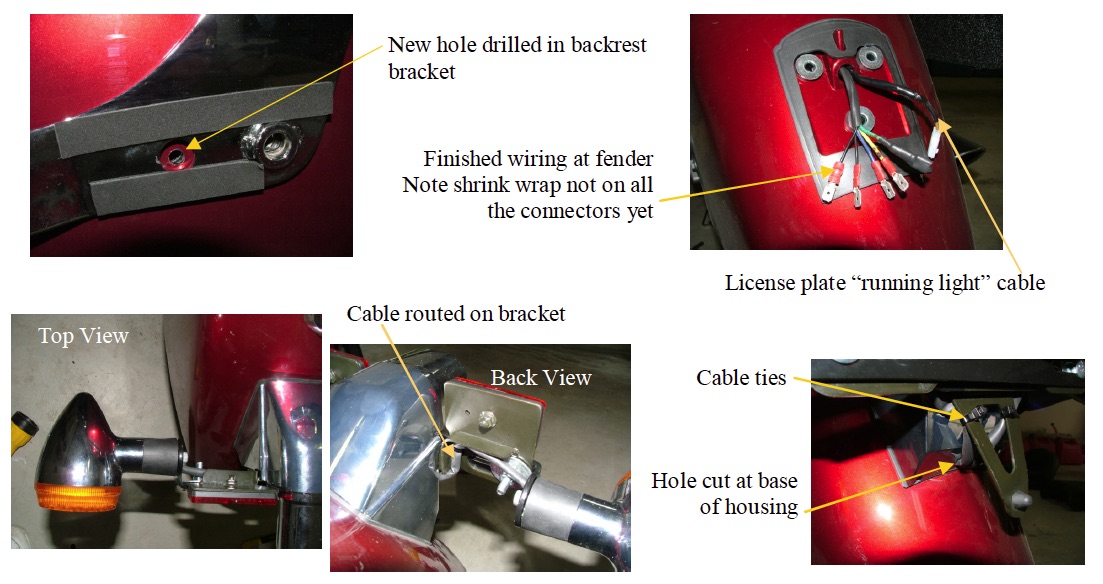
The brake/running light wires run down the right side of your back fender. You will route your new turn signal wiring harness down the left side in the same manner. You will notice that the brake/running light wiring goes through a hole in the fender. (My Honda-line backrest bracket also has a hole there too, which the cable passes through.) Take off the same 3 bolts as done earlier and remove the chrome fender rail cover on the left side of the bike. Notice that there is no hole in the fender. Thus, you need to drill one! If you do not have a back rest, reach behind the fender and find the "hole" in the metal bracket that you need to go through. I simply drilled a 5/16 inch hole thru in the center of the backrest bracket... it worked perfect.
Now, plug in your harness and carefully route the wiring around the frame and attach it to the chrome fender frame cover. Then take the end through the fender hole and down the frame to the base of the inside of the fender. Reassemble the chrome fender frame cover using the 3 bolts. I attached the cabling to the inside of the fender supports using cable ties. (Do not pull these completely tighten these until you finish all the wiring.)
Remove the 3 nuts the hold the license plate housing to the back of the fender. Remove the license plate housing being careful to disconnect the running light cable. Set the unit aside for now.
Remove the rubber gasket that holds the existing license plate light cable in place... and take it off the cable. You should have enough room now to pull the new wiring through the same hole. Do so. Make sure the cabling inside the fender is where you will be attaching it... then, with about 3 inches of the harness coming through the fender, cut off the remaining cable. Strip and put on your quick connects on each wire. Cover each of the connectors with shrink wrap so as to protect the connection.
I make the green (ground) cable a male and all the rest female... just so as to not accidentally mix them up later. Also, leave a little part of the cable above the shrink wrap uncovered so you can ID what color it is.
Assembly of the Turn Signals and License Plate Housing:
Attach you turn signals to your new turn signal bracket. Note that the bracket has a “twist” and sits at an angle on the license plate housing so that the signals end up perpendicular to the ground. (Hold it on the plate holder and you’ll see what I mean.) So, get the correct turn signal (with the lens cap screw down) on the correct side of the bracket.
Attach the turn signal bracket (with the lights on it) onto the license plate holder using a 1" long stainless steel 1/4" carriage bolt, fender washer and a locking nut. Route the turn signal wiring around the back of the license plate holder... following the shape of the bracket. Using cable ties, loosely attach the wires to the bot tom of the plate holder. Slowly cut a notch about the size of a number 2 pencil in the bottom of the chrome license plate housing to route the wires through. (I used a roto-zip and carefully free-handed the cut.)
Pull the wiring through the back-side of the housing and out the same location as the existing license plate light cable. Cut and attach your 5 quick connects to the ends of the cables. Place shrink wrap on each one to protect them. Make sure to leave about 3 inches of cable where the wires come out so you can attach them to the connections coming out of the fender.
Make all of your electrical connections and reassemble the license plate housing to the fender using the three original nuts. Now is the time to tighten up all of your wire cable ties so that your wiring harness does not move around inside the fender. Finish by heat shrinking any exposed cabling.
Final Notes:
*** When I had finished the turn signals and wiring harness... I tested the wiring before putting it on the bike. I simply completely finished the assembly and wiring of the license plate housing and turn signals. I then put temporary connectors on the wiring harness. I laid the license plate/turn signal housing on a towel on the seat pan... plugged everything up and turn the bike to test all the lights. It worked first time. (If it had not.... it would have been much easier to chase the problem before the cables were run.) If you do this... make sure all your connections are temporarily covered with electrical tape to keep from short circuiting anything.
*** Heat all of your shrink wrap AFTER you get your cables and connectors where you want them. Shrink wrapped wires tends to hold their shape after it is shrunk. (A blow dryer will work, but a real heat gun is much hotter and quicker.)
*** I’m also using this with the Kisan "signalMinder" turn signal canceling system. It works fine. If you do use the "flasher option" in the signalMinder system... you do get the rear turn signals also acting as "running lights" at 1/3 brightness (in addition to your LED ring). The Turn signals therefore are not quite as "red", but I’m happy with the look.
*** If you’ve got any question... feel free to email me at: rickfrost@aol.com
Good Luck and Safe Riding,
Ranger Rick :)
Please note: all of the above content if for information purposes only. I am not liable to anyone in any way for it being correct or how any of the above information it is used. Modify your motorcycle at your own risk.
This website and it's contents are not affiliated with with Honda Motor Company, or any other group or organization. Performing the modifications listed within the website is done at your own risk. Developed and hosted by McLauthlin Technologies, LLC. Send questions, comments, or additions to